Volkswagen Golf Service & Repair Manual: Removing and installing brake master cylinder, RHD vehicles
 Note Note
| If there are problems with the brake servo, first check the
brake servo vacuum system
→ Chapter. |
| Special tools and workshop equipment
required |
|
|
|
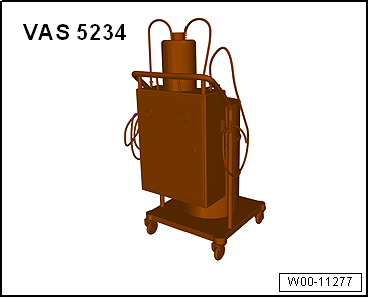
| Brake filling and bleeding equipment -VAS 5234- |
|
|
|
| Torque wrench -V.A.G 1331- |
|
|

|
| Fitting location of brake master cylinder in RHD vehicles: |
| 1 - |
Brake servo and brake master cylinder |
| 2 - |
ABS hydraulic unit -N55- and ABS control unit -J104- |
| – |
If vehicle has a coded radio, note radio code or, if
necessary, request it. |
| Vehicle with diesel engine: |
| – |
Remove engine cover panel
→ Rep. gr.10. |
The fuel system is pressurised.Risk of injury due to fuel which may
spurt out.Wear eye pretection.Wear protective gloves.Release pressure:
place clean cloth around connection, and carefully open connection.
|
|

|
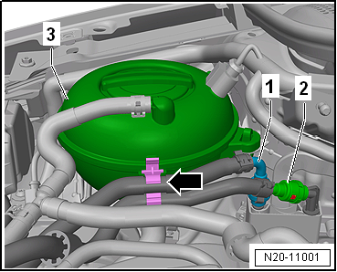
| – |
Release and pull off fuel supply lines
-1- and -2-. |
| – |
Separate plug-in connectors
→ Rep. gr.20. |
| – |
Unclip fuel lines -1- and
-2- from retainer
-arrow- on coolant reservoir
-3-. |
|
|
|
| – |
Remove securing bolts -2-. |
|
|

|
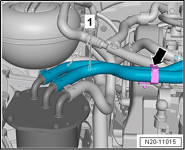
| – |
Open retainer -arrow- and
unclip fuel lines -1-. |
| – |
Then lay fuel filter to one side. |
|
|
|
| – |
Release electrical connector -1-
and pull off. |
| – |
Release catches using a screwdriver
-arrow-. |
| – |
Place coolant expansion tank onto engine. |
| – |
Remove upper toothed belt guard
→ Rep. gr.15. |
|
|

|
| Vehicles with manual gearbox: |
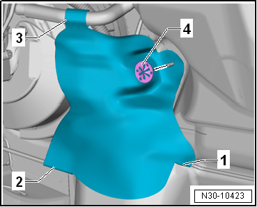
| – |
If present, remove heat shield. |
| – |
To do so, remove clamping washer -4-
from plenum chamber bulkhead. |
| – |
Open snaps -1- to
-3- on heat shield. |
|
|
|
| – |
Pull return hose -2- for clutch
sender cylinder -3- off brake fluid
reservoir -4-. |
| – |
Seal return hose -2- for clutch
master cylinder -3- with sealing
tool -T10249--1- or hose clips to
25 mm -3094-. |
| – |
Raise and tie return hose -2-
in place. |
|
|

|
| Vehicles with air conditioning: |
| – |
Evacuate refrigerant circuit
→ Heating, air conditioning; Rep. gr.00. |
| – |
Unscrew nuts -2- on refrigerant
line -1-. |
| – |
Remove refrigerant line -1-. |
| Continuation for all models: |
Note
| The illustration shows installation position of ABS
hydraulic unit -N55- and ABS control unit -J104- on a LHD
vehicle. |
| – |
Place sufficient lint-free cloths in area of engine. |
| – |
Draw off as much brake fluid as possible from brake fluid
reservoir using brake filling and bleeding equipment -VAS 5234-. |
|
|

|
| – |
Remove heat shield -1- if
present. |
| – |
To do this, unscrew bolt -3-. |
| – |
Pull heat shield -1- upwards
out of retainers -arrows- on brake
fluid reservoir -2-. |
|
|

|
| – |
Release connector -1- and pull
off brake light switch -F--2-. |
|
|

|
| – |
Release electrical connector -2-
for brake fluid level warning contact -F34- and pull it off
brake fluid reservoir -1-. |
|
|

|
| – |
Pull out spreader rivet -3- in
-direction of arrow-. |
| – |
Pull brake fluid reservoir -1-
upwards off brake master cylinder -2- |
|
|

|
| – |
When doing this, gently press refrigerant line
-1- upwards. |
|
|
|
| – |
Unscrew brake lines -1- from
brake master cylinder -3-. |
| – |
Seal brake lines with sealing plugs from repair kit Part
No. 1H0 698 311 A. |
| – |
Remove heat shield -3-. |
| – |
Carefully remove brake master cylinder from brake servo. |
| Install in reverse order of removal, observing the
following: |
| – |
When assembling brake master cylinder with brake servo, make
sure push rod is properly positioned in brake master cylinder. |
| – |
When joining brake master cylinder to brake servo, make sure
seal
→ Item is properly seated. |
| – |
Ensure that seals
→ Item are correctly seated in brake master cylinder. |
| – |
Moisten sealing plugs
→ Item with brake fluid before pressing brake fluid
reservoir into brake master cylinder. |
| – |
Bleed brake system
→ Chapter. |
| Vehicles with manual gearbox: |
| – |
Bleed clutch mechanism
→ Rep. gr.30. |
| Vehicles with air conditioning: |
| – |
Charge refrigerant circuit
→ Heating, air conditioning; Rep. gr.00. |
| → Chapter „Assembly overview - brake servo/brake master
cylinder, RHD vehicles“ |
| → Chapter „Connecting brake lines to hydraulic unit, RHD
vehicles“ |
| Toothed belt guard
→ Rep. gr.15 |
| Air conditioning
→ Heating, air conditioning; Rep. gr.87 |
| Front bleed valves
→ Chapter „Assembly overview - front brake caliper“ |
| Rear bleed valves
→ Chapter „Assembly overview - rear brake caliper“ |
|
|

|
Special tools and workshop equipment
required
Brake filling and bleeding equipment -VAS 5234-
...
Vacuum pump for brake servo, diesel
vehicles
Vacuum pump for 4-cylinder diesel engine (1.6 l, common
rail):
The vacuum p ...
Other materials:
Specified values for wheel alignment, torsion beam axle, Golf
These specifications apply to all engines.
Explanations regarding PR numbers
→ Chapter „Vehicle data sticker“.
Front axle
Basic
running gear
Sports
running gear
Raised
running gear
DCC
running gear
...
Legislative conditions
The manufacturer is issued with a general operating permit
(GTA in accordance with § 20 StVZO (German road traffic and
licensing regulations) and EU operating permit) for the overall
vehicle with all parts for specific conversions.
Conv ...
Variable luggage compartment floor
Fig. 103 In the luggage compartment: lifting
the variable luggage compartment floor
Fig. 104 In the luggage compartment:
variable luggage compartment floor folded up
First read and observe the introductory information
and safety warnings The variable luggage compartment floor is height-a ...
© 2016-2024 Copyright www.vwgolf.org


 Removing and installing brake master cylinder, LHD vehicles
 Vacuum system