Volkswagen Golf Service & Repair Manual: Removing and installing wheel bearing housing, multi-link suspension,
four-wheel drive
| Special tools and workshop equipment
required |
|
|
|
| Torque wrench -V.A.G 1332- |
|
|
|
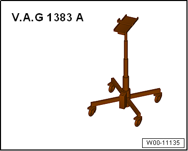
| Engine and gearbox jack -V.A.G 1383 A- |
| – |
Loosen outer drive shaft threaded connection
→ Chapter. |
 Caution
| Wheel bearings must not be subjected to load after
bolt securing drive shaft to wheel hub has been
loosened. |
| If wheel bearings are loaded with weight of vehicle,
bearing will be damaged. This reduces the service life
of the wheel bearing. |
| It is not permissible to loosen drive shaft bolt
more than 90° if vehicle is standing on its wheels. |
| Do not attempt to move the vehicle without the drive
shafts fitted as this would damage the wheel bearing. If
a vehicle nevertheless has to be moved, comply with the
following: |
| Install an outer joint instead of the drive shaft. |
| Tighten outer joint to 120 Nm. |
|
| – |
Remove wheel bearing unit
→ Chapter |
| – |
Remove heat shield
→ Brake system; Rep. gr.46. |
| – |
Remove spring
→ Chapter. |
| Vehicles with vehicle level sender |
|
|
|
| – |
Remove retainer for rear left vehicle level sender-2-. |
| Vehicles with stone guard |
|
|

|
| – |
Remove spreader rivet -1-. |
| – |
Unscrew bolts -2- for stone
deflector -3-. |
| Continuation for all vehicles |
| – |
Disconnect electrical connector from ABS speed sensor and
electromechanical parking brake motor. |
|
|

|
| – |
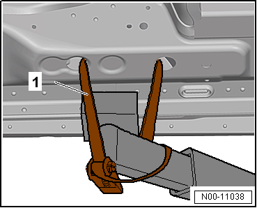
Use tensioning straps -T10038--1-
to strap vehicle to support beams of lifting platform on both
sides. |
 WARNING
| If the vehicle is not strapped down, there is a
great danger that the vehicle will slip off the lifting
platform! |
|
| – |
Position engine and gearbox jack -V.A.G 1383 A--1-
under track rod and press upwards slightly. |
|
|
|
| – |
Unscrew bolts -2- and
-3- one after the other. |
|
|

|
| – |
Remove engine and gearbox jack -V.A.G 1383 A--1-
from under track rod. |
|
|

|
| – |
Unscrew nut -1- and remove bolt
-2-. |
|
|

|
| – |
Unscrew nut -1- and pull out
bolt -2-. |
| – |
Take out wheel bearing housing -4-. |
| Install in reverse order of removal, observing the
following: |
| It is essential to follow specified sequence of work steps
below! |
| – |
Fit wheel bearing housing. |
|
|

|
| – |
Insert bolt -4- with washer
-3-. |
| – |
Only hand-tighten nut -1-. |
|
|
|
| – |
Insert bolt -2- and tighten nut
-1- only hand-tight. |
| – |
Insert bolt -3- and tighten
only hand-tight. |
|
|
|
| – |
Position engine and gearbox jack -V.A.G 1383 A--1-
under track rod and press upwards slightly. |
| – |
Screw in bolts -2- and
-3- by hand. |
| – |
Remove engine and gearbox jack -V.A.G 1383 A--1-
from under track rod. |
| – |
Install wheel bearing unit
→ Chapter |
| – |
Install heat shield
→ Brake system; Rep. gr.46. |
| The threaded connections of the wheel bearing housing may
only be loosened and tightened in the unladen weight position
→ Chapter. |
|
|
|
| – |
Detach engine and gearbox jack -V.A.G 1383 A- with support
-T10149- from wheel hub. |
|
|
|
| Do not tighten bolts securing trailing arm to wheel bearing
housing until all other suspension components (especially spring
and shock absorber) on that side are fitted. To tighten, wheel
suspension must be in extended position. Only then do trailing
arm and wheel bearing housing move to the necessary position
-arrows-. |
| – |
Install coil spring
→ Chapter. |
|
|

|
| – |
Tighten bolts -2- and
-3-. |
| → Chapter „Assembly overview - suspension, multi-link
suspension, four-wheel drive“ |
| → Chapter „Assembly overview - suspension strut, shock absorber,
spring, multi-link suspension“ |
| → Chapter „Assembly overview - trailing arm“ |
| → Chapter „Assembly overview - track rod“ |
| → Chapter „Assembly overview - rear vehicle level senders,
multi-link suspension, front-wheel drive“ |
| → Chapter „Loosening and tightening threaded connections of
drive shaft“ |
| → Chapter „Torque settings for wheel bolts“ |
| Bolts for heat shield, brake caliper and brake disc
→ Brake system; Rep. gr.46 |
| On vehicles with vehicle level sender, carry out basic
settings for wheel damper electronics → Vehicle
diagnostic tester. |
| On vehicles with vehicle level sender, carry out basic
adjustment of headlights
→ Electrical system; Rep. gr.94. |
|
|
|
Special tools and workshop equipment
required
Torque wrench -V.A.G 1332-
...
Special tools and workshop equipment required
Fitting sleeve -3241/4-
Hub grease cap puller -VW 637/2-
Torque wrench -V.A.G 1332-
...
Other materials:
Introduction
This chapter contains information on the following subjects:
→ Function
When the toll card system is switched on and functioning, tolls will be charged
automatically when driving through a toll booth. The charge will be confirmed by
an acoustic signal. The charges will be relayed ...
Fault in the function of the automatic gearbox
First read and observe the introductory information
and safety warnings Emergency programme
There is a fault in the system if all the displays on the instrument cluster
for the selector lever positions have a light background. The automatic gearbox
is running in an emergency programme. The ...
Removing and installing trim for operating and display unit
Removing
–
Starting at bottom, unclip trim for operating and display
unit -1- from operating and display
unit -2- and remove it.
Installing
Note
Before installing, chec ...
© 2016-2024 Copyright www.vwgolf.org

 Removing and installing wheel bearing housing, multi-link suspension,
front-wheel drive
Removing and installing wheel bearing housing, multi-link suspension,
front-wheel drive Removing and installing wheel bearing unit, torsion beam axle